This post is also available in:
![]()
When you open a CAD model in Slicer, in most cases it will be displayed aligned as it was designed in the CAD tool. This is understandable and makes sense. But is the orientation of the part at design time automatically the best orientation for printing?
How do you properly align a print object for printing? Three criteria must be taken into account for the optimum alignment of the component: Printing time, quality and strength. This means using as little support material and layers as possible, aligning curvatures along the Z-axis, and considering the influence of tensile and bending forces on the part.
Rarely will you be able to meet all three criteria equally well. In this article, I’ll go into more detail about the above points and show you ways to work around potential problems.
Align print objects correctly for 3D printing
Determining the optimal orientation of an object for printing can be quite a challenge, depending on the geometry of the model. Three essential criteria have to be reconciled. That means you have to find the right balance while getting the most out of each area. As you can imagine, this is often not so easy. These criteria to consider are:
- Print time
- Quality
- Strength
But what influence does the orientation of the component have on these criteria? Well, proper part alignment can greatly reduce printing time, as well as increase the visual quality and stability of your part. The different influences of the orientation of the component can be shown very well by the print preparation of the letter T in the slicer.
Alignment:
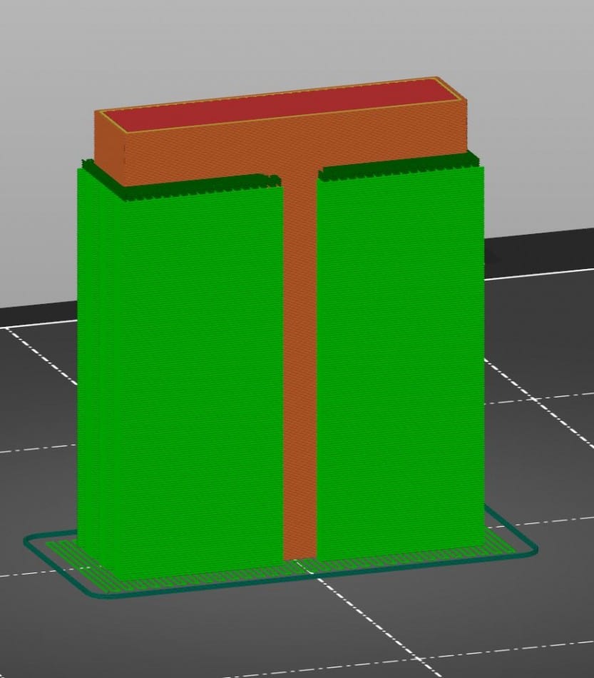
The letter T is printed in normal orientation.
Advantages:
The optical quality along the Z axis is optimal.
Disadvantages:
Due to the support material, the printing time is extended.
The support material affects the quality of the surface above the support material.
Low stability when force is applied at the transition.
Calculated printing time: 1 hr. 20 min.
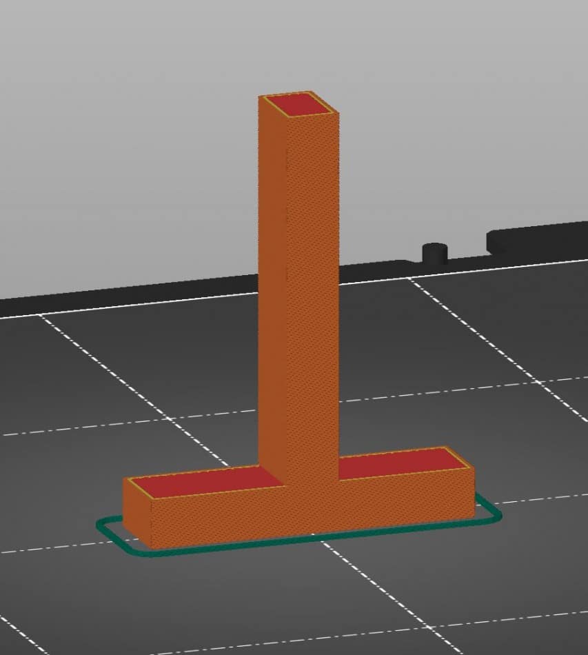
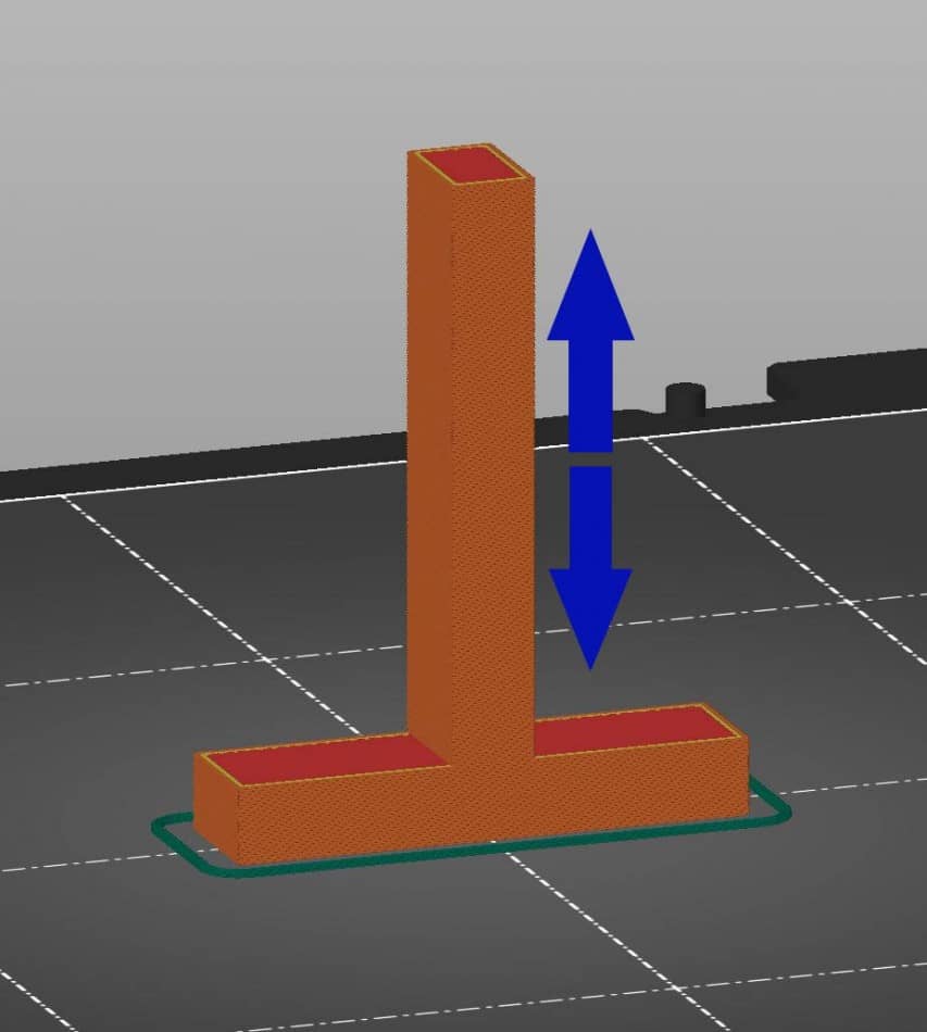
Alignment:
The letter T is turned upside down.
Advantages:
The printing time is reduced to about 1/3 of the original printing time.
The optical quality along the Z axis is optimal.
Disadvantages:
Low stability when force is applied at the transition.
Calculated printing time: 33 min.
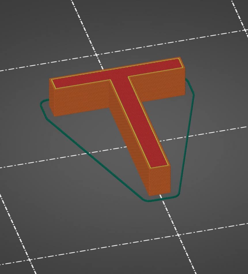
Alignment.
The letter T is printed horizontally.
Advantages:
The printing time was once again almost halved.
Maximum stability is achieved by only a few layers along the Z-axis.
Disadvantages:
Due to the large visible surface area, the optical quality of the printout is somewhat compromised.
Calculated printing time: 19 min.
As can be seen from these examples, it is not always possible to get the optimum out of all areas. As mentioned, it is important to find the right balance or the right setting for the intended use of the component. If you’re printing a prototype, you can focus more on speed and stability. If it is the final part that goes to the customer, you should rather put more emphasis on quality than speed.
Reduced printing time due to optimum component alignment
The orientation of the print object on the print bed can significantly affect the print duration. Positive as well as negative. As the example above has shown, despite the very simple model, the difference between the worst and the best alignment is almost exactly one hour. Two main factors are decisive for this. The use of support material and the number of layers along the Z axis.
Support material
Depending on the orientation of the part, you may or may not need support material for a successful print. The fact that the need for support material extends the printing time has probably been known for a long time anyway. However, there are different ways to print support material, which in turn have different effects on the printing time, but also on the quality of the printout.
The support that is printed with the same material as the actual print object has the least influence on the printing time. Whereby the word “low” is to be understood relatively here. The calculation of the printing time with support material performed in the previous section is based on exactly this variant. And even here, the printing time was extended by one hour.
The variant with a separate support material in a multi-extruder printer has the most influence on the printing time, e.g. when PVA is used as support material for PLA. Here, as long as the support material is required, the pressure nozzle must be changed and prepared again and again during each shift in between. Each of these nozzle changes takes additional time. The calculated print time for a multi-extruder support on a Flashforge Dreamer is 2 h 57 min. and has thus more than doubled.
The third variant, as is not hard to guess, lies between the first two in its effect. This variant is also a multi-extruder support and is called Dense Support. In this process, only a few webs are printed with the usually soluble secondary material shortly after or before the transition to the actual print object. The majority of the support, on the other hand, is printed with the print material itself in order to reduce the time required for nozzle changes.
Number of layers
But it is not only the use and type of support material that has a negative impact on construction time. How many layers have to be printed along the Z-axis is also crucial. The fewer layers that have to be printed on top of each other, the shorter the printing time as a rule.
Again, I would like to refer to the comparison at the beginning of the article. The horizontal orientation with the fewest layers along the Z-axis was by far the orientation with the shortest printing time.
Higher quality due to optimal alignment of the component
The best optical quality of a component is achieved along the Z axis. Right. Exactly along that Z-axis, which we should actually avoid because of the negative influence on the print duration. And with this at the latest, it should also be clear why we can only achieve the best quality and the lowest print duration together in rare cases.
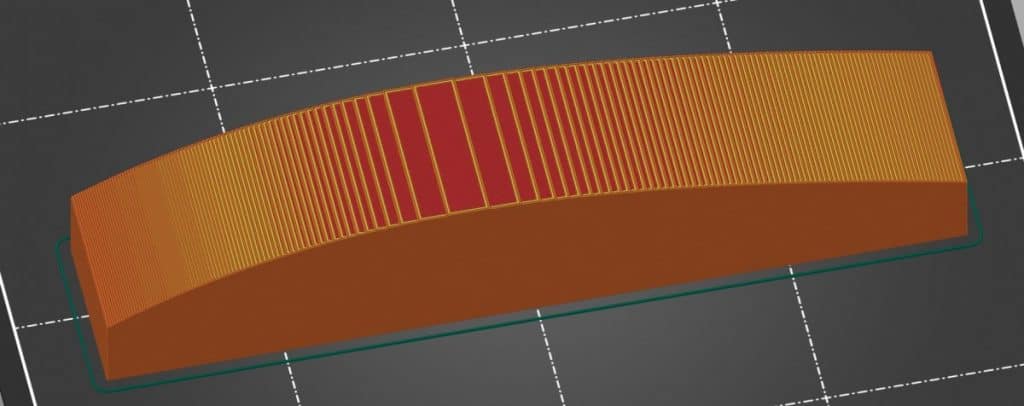
Curved or angled surfaces in particular achieve the best results when aligned along the Z axis. The reason for this is the so-called staircase effect. Since 3D printing is layer upon layer, curvatures along the X and Y axes result in a stepped transition, depending on the defined layer height and the size of the surface.
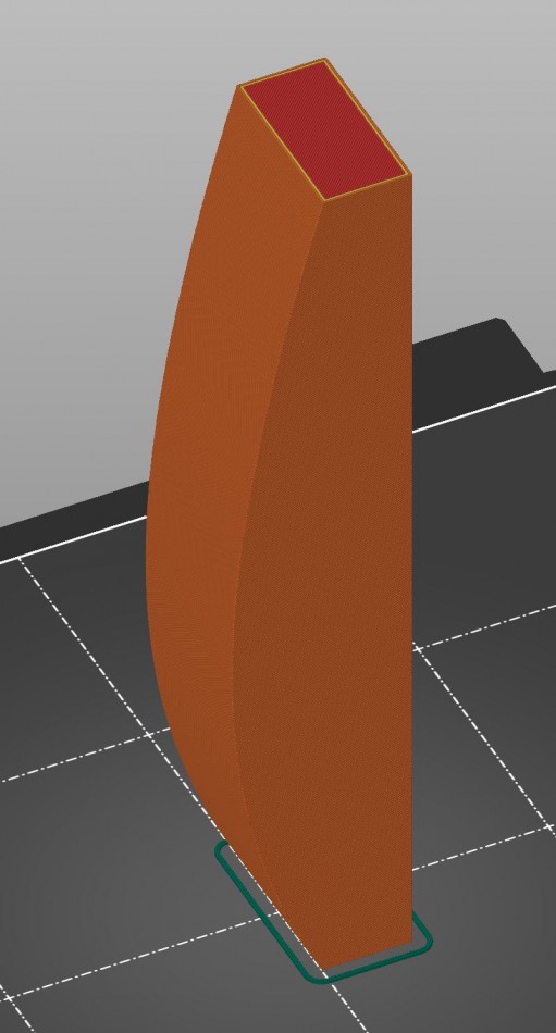
If this curvature is aligned parallel to the Z axis, this effect is not noticeable because the layers are again more or less directly on top of each other. This makes the object look more qualitative.
However, as already mentioned, this plus in quality is reflected in the duration of the print. The latter variant with the correct alignment extends the printing time by about 30 minutes.
Of course, there will always be models in which there are curvatures on several sides and it is therefore not so easy to determine the optimum pressure alignment. However, in such cases, it is often the case that the optimum alignment results on its own due to the expected force acting on the component. If not, it is advisable to orientate the component so that the step effect occurs on that side which will later be least visible.
Higher strength due to optimum alignment of the component
FDM 3D printing produces components by printing many layers on top of each other. These superimposed layers create a so-called anisotropic component. Anisotropy describes the directionality of properties and processes.
Referring to FDM 3D printing, this means that an FDM printed part has different strength on each axis. Ok, not every axis. X and Y are usually equated. The Z axis, however, does not.
For a better understanding, let’s use the example with the letter T from the beginning of the article again. If the letter T is printed normally or upside down, the vertical bar is built up layer by layer. If pressure is now applied to this beam from the side or if the beam is pulled in opposite directions, the component already breaks or tears with a manageable force influence.
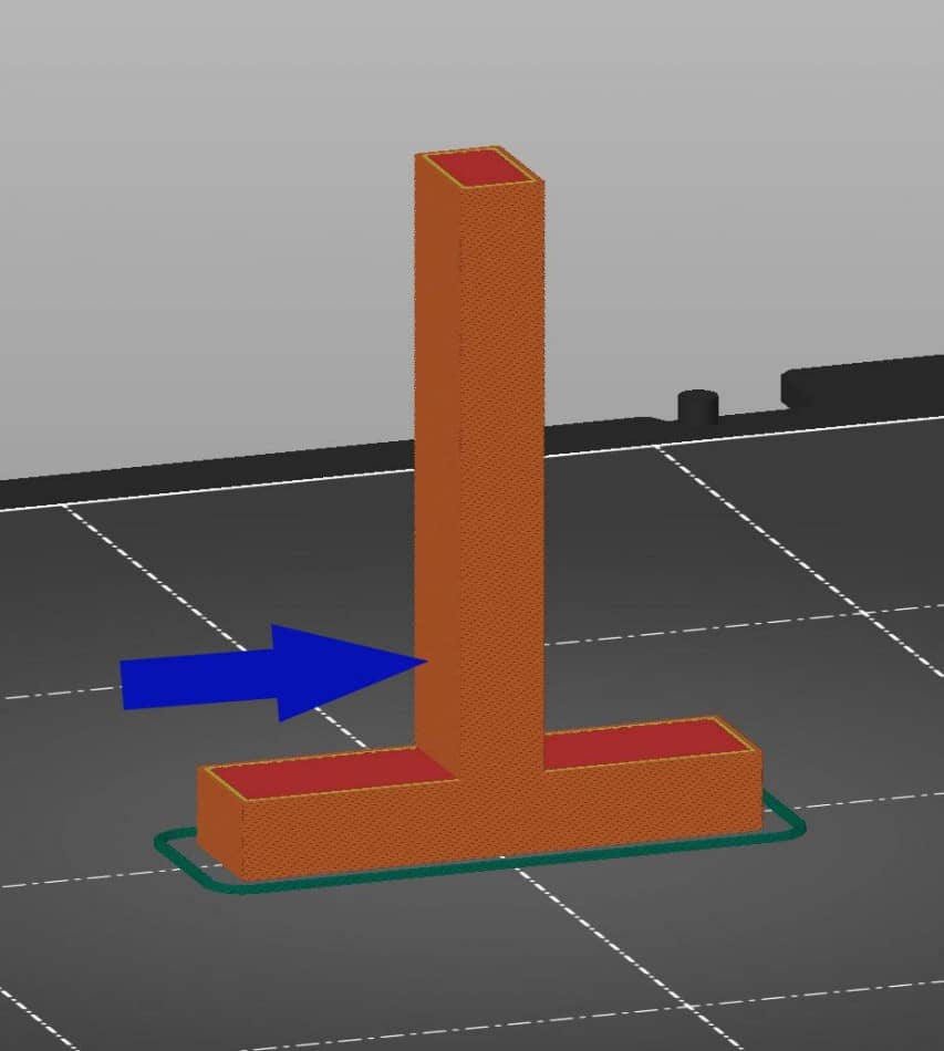
However, if the letter is printed horizontally, the layer structure is also correspondingly different. If pressure is now applied or pulled on the same areas as before, a far greater amount of force is required this time to damage the component, if this is possible at all.
Therefore, if it is clear from the outset where and on which points of the component pressure will be applied, this should also be taken into account accordingly when aligning the component. Even if this does not always have a positive effect on the quality of the component. No one needs a component that is beautiful to look at but breaks at the slightest application of force.
Optimal position of the print object on the print bed
The position of the print object on the print bed is not directly related to the orientation of the component. It does not affect the quality and strength of the component. The only thing that positioning can have a massive influence on is the print duration. As small as the influence is for a printer with a small print bed in single-extruder printing, as large is the influence for a printer with a large print bed in dual-extruder printing.
With a small printer and single-extruder printing, positioning hardly matters. Whether you place the object near the home position of the print head or in the other corner, the print head moves once to the designated position and then starts printing.
However, if you use a larger dual-extruder printer, things look quite different. Each time the nozzle is changed, the printhead moves to a specific position to prepare the nozzle for printing. The more often the material is changed, the more often this positioning run and preparation must be performed.
These positioning runs for the continuous nozzle changes take up a lot of time. As explained earlier in this article, the printing time doubles between a print job with a support structure made of the same material and a print job with a support structure made of a different material. The closer you place the so-called priming tower to the print object, the shorter the positioning runs for preparing the nozzles.
Conclusion
In summary, it can be stated that the component alignment has a very large influence on the printing duration, quality and stability of the respective component. As mentioned several times in the article, it is almost impossible to achieve the optimum for all factors, especially for components with complex geometry. The factors of quality and print duration in particular sometimes get in each other’s way here. The bottom line is that it’s all about finding the right balance between the three factors to create a really good print result in a reasonable print time.